Documentation User manual
Inspection, reports and setup sheets
After a part is cut, the touch probe measures it against the design. Studio writes what it measured, with the twin's estimate beside it, into an inspection report. Before a part is cut, a setup sheet tells the operator how to set the job up. Both are in the Pro edition.
Measuring a part with the touch probe
Measure a part where it was cut, before you take it off the machine. The Measure the part card is in Setup, step Zero, under the probe card. It compares the part with the design of its CAM job: each feature's size, fit and tolerance. In 1.0 the card measures on the twin, as the probe card does. When the twin follows a real machine, measure there with the machine's own control.
You need:
- The part, cut and still held as it was cut. Do not move the work zero: the positions are measured from it.
- The touch probe in the spindle, calibrated on its ring gauge. See Probing.
- The program's CAM job: a program made in CAM, or by the AI assistant.
Note
Measuring is in the Pro edition. In the other editions the card shows with a Pro label, and Start measuring… says how to try it. Records and reports made before open in every edition.
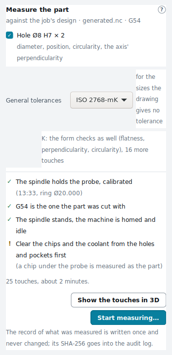
To measure:
- In Setup, click the step Zero. Result: the card says what it compares the part with: the program and the work offset it was cut with, for example G54.
- Choose the features to measure. All are chosen at first. Result: each feature says what the probe measures on it. A feature the probe cannot measure is grey and says why.
- Under General tolerances, choose the class for the sizes that have no tolerance of their own. Add H, K or L for the form checks (see Tolerances). Result: the card says how many touches it makes and about how long they take.
- Read the checks: the probe in the spindle and calibrated, the work zero the one the part was cut with, the spindle standing, the machine homed and idle.
- Clear the chips and the coolant from the holes and pockets. A chip under the probe is measured as the part.
- To see where the probe will touch, click Show the touches in 3D. Result: the 3D view shows the touches from the side and the touches downward.
- Click Start measuring…. Result: the probe touches each feature, and the card says what it measures now.
⚠ Warning
The probe moves at feed rates near the part. Keep hands and tools away from the machine while it measures.
What is measured:
| Feature | Checks |
|---|---|
| Pocket, contour | Its walls' size and position, its floor's depth |
| Hole, boss | Diameter and position |
| Slot | Width and depth |
| Face | Depth |
| Chamfer | Width, depth and angle |
| V groove (engraving or V-carving with a V-bit) | Width, depth, angle and offset from its line |
| Engraving with an end mill, thread, 3D surface | Not measured |
The form checks add flatness, perpendicularity, circularity and straightness where they apply (see Form).
When the probe is done, the Measurement results card takes the measuring card's place. It shows:
- when the part was measured, how long it took, and the program;
- how many checks are within tolerance, how many out of tolerance, and how many are not judged: not judged in the twin (its cells there coarser than a quarter of the tolerance), no tolerance or not measured;
- each check out of tolerance, with its measured value, its limit and how far it is over or under;
- for the first feature out of tolerance, the most likely cause and what to do next.
In 1.0 the probe measures the part the twin cut, so the cause comes from the twin alone. If the twin's own part is out of tolerance at the same touches, the program cuts it so: change it in CAM. Otherwise the measured value and the twin's estimate differ only by what the twin models of the probe (the ball's effective radius and, for a typical probe, its pretravel, which a calibration on the ring gauge takes out) and by the size of the twin's cells where the probe touches. Calibrate the probe on the ring gauge and measure again. The causes are suggestions, not a diagnosis.
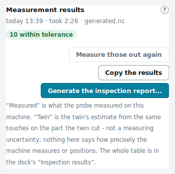
The card's keys:
- Measure those out again: measures the checks out of tolerance once more, for example after you calibrated the probe again.
- Copy the results: copies the table as text, one column per tab, for a spreadsheet.
- Generate the inspection report…: writes the report (see The inspection report).
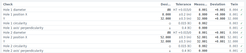
The whole table is in the dock's Inspection results tab. Each row is one check, with its Design value, its Tolerance, what was Measured, the Deviation, the Twin estimate and the verdict: ✓, or ✗ with how far it is out. Rows out of tolerance are red, and the 3D view marks the results on the part.
Each inspection is kept as a record. The record is written once and never changed, and its SHA-256 goes into the audit log (see Checking a copy against the audit log).
The AI assistant measures the same way, with the inspect_part tool. Ask, for example: "Inspect the part of bracket.nc with the probe".
- The assistant says what it will measure, and how many touches and seconds the form checks add.
- Confirm before the probe moves. Result: the answer lists each check with its measured value, the twin's estimate and the verdict.
Tolerances
Each check is judged against a tolerance. A size's own tolerance or fit comes from the CAM job, as it was typed in the size's field (for example 8 H7). The other sizes take the general tolerance.
General tolerances (ISO 2768-1)
ISO 2768-1 has four classes: f (fine), m (medium), c (coarse) and v (very coarse). A size without its own tolerance takes the class's tolerance for its size range. Choose the class on the card, under General tolerances. Or ask the assistant for it, for example: "Inspect it to ISO 2768-m".
Form: flatness, perpendicularity, circularity, straightness (ISO 2768-2)
Add H, K or L after the class, for example "mK". The probe then also checks the form:
| Check | How it is measured |
|---|---|
| Flatness | A floor touched on a 3 × 3 grid |
| Perpendicularity | A wall, or a hole's axis, touched again at a second depth |
| Circularity | A hole or boss touched at 8 points |
| Straightness | A long wall touched at 3 to 8 points |
The card, or the assistant, says how many more touches the form checks take before the probe moves.
Note
A touch probe that is not calibrated in each direction has its own lobing. The report says how large the twin's probe model takes it to be, next to each circularity.
Fits (ISO 286)
A size written with its fit, for example Ø8 H7, is judged against the fit's zone. See Fits and tolerances.
Chamfers and V grooves
Chamfer widths, depths and angles, and V-groove widths, depths and angles, take ISO 2768-1 class f unless you give their own tolerance.
What the twin estimates
The twin runs the same touches on its simulated workpiece. Its estimate is what the program cut in the twin. When the measured value and the estimate differ, look at the machine and the set-up: the tool's length, the work zero, the fixture, a worn tool.
The twin's estimate is a calculation from its physical models. It is not the machine's measuring uncertainty.
The inspection report
Every inspection is kept as a record. From a record, Studio writes the report:
- a CSV file (UTF-8), for a spreadsheet;
- a PDF file, for printing and filing.
The report lists the job, the setup, the tools, the probe and its calibration, and for each feature: the nominal size, the tolerance and its basis, the twin's estimate, the measured value, the deviation and the verdict. It says why a feature was not measured, and shows the twin's workpiece from above.
To write it, ask the assistant, for example: "Write the report of the last inspection". The same record gives the same files, byte for byte.
Where the reports are
Inspection reports and setup sheets are in the reports folder:
- Windows: Documents\Twinwright Studio\Reports
- Linux: ~/Documents/Twinwright Studio/Reports
If you moved the programs folder in the settings, the reports folder is inside it.
Checking a copy against the audit log
Studio records the SHA-256 of every record, report and setup sheet in its audit log. Each entry is chained to the one before it. You can check a copy that someone sends you:
- Ask the assistant: "Check this file against the audit log", with the file's path.
- Or run, on the computer where it was written:
mc1sim --inspect-verify <file>
The answer says whether the log holds the file's SHA-256, when it was written, and whether the log's chain is whole. A copy changed by a single bit is not found.
Setup sheets
A setup sheet is one page for the operator at the machine. It says what to set up and in which order. Studio writes one for each job, in the language you use. The paper is A4, or Letter in the United States and Canada.
To write one, ask the AI assistant, for example: "Write the setup sheet for bracket.nc". The assistant uses the setup_sheet tool.
Note
Setup sheets are in the Pro edition.
What a setup sheet shows
- Programs: Each program's name, version and number of lines, and the first 8 hexadecimal digits of its SHA-256. Compare them with the program loaded on the machine.
- Blank and fixture: The blank's size and material, and how the twin sets it up. For a vise: the parallels, the grip and how far the blank stands over the jaws.
- Tools: Each tool's number, kind, diameter, flutes, stickout and spec, and the operations that use it.
- Each setup: How the part gets there (turned over, held another way), where the work zero is, and the probe cycles that find it. The cycles have the names they have on the probe panel.
- Travel: The lowest and highest X, Y and Z the program moves to, in work coordinates.
- Z clearance: See Z clearance.
- Operations: Each operation's strategy and how it goes into the material, its tool, speed, feed and depth, and the time it takes.
- Top view: The blank, the vise jaws, the work zero and the outline of each feature.
- Notes: The CAM's notes, in English.
The times are estimated from the program: its feeds, and the machine's rapid rate and acceleration. Tool changes are not counted. A trial run in the twin gives times with acceleration and deceleration counted.
Z clearance
For each setup, the sheet checks that the touch probe and each tool get over the set-up. It also checks that each tool reaches the program's highest and lowest points. The heights are the twin's Z budget's, measured from the table top.
| Item | Has to reach |
|---|---|
| Touch probe | 1 mm over the set-up's highest point, with Z near the top of its travel |
| Each tool, up | 0.5 mm over the set-up's highest point, and the program's highest point |
| Each tool, down | The lowest point of its own operations |
Each row says Enough, or how many millimetres short it is, in red.
Caution
A row in red means that the program cannot run on this set-up. Use a tool with less stickout or a shorter probe, or hold the part lower, for example with clamps.
A clamp can stand higher than the program's highest point. The sheet then says so: the program must not cross the clamp. A trial run in the twin checks that.
Printing and signing
- Open the setup sheet in a web browser.
- Print it. Result: each setup after the first starts on a new page.
- At the machine, fill in the box at the end: the operator, the date and the first-article inspection (pass or fail, and the number of its inspection report).
A new setup sheet of the same job replaces the file. Its SHA-256 is recorded in the audit log.