Bring the shape
SVG and DXF drawings (layers, blocks, splines, units), text in a single-line or outline font, simple shapes and formulas, or meshes for 3D: STL, OBJ, 3MF and glTF.
Studio computes toolpaths for this machine. Give it a drawing, a mesh, a line of text or a shape your AI describes; it writes the program, sets spindle speed, depth and feed from the twin's physics, and runs it to the end in the twin before you see it.
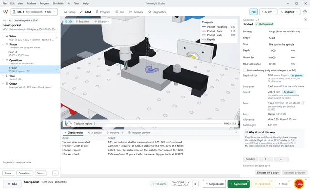
Every step works in the CAM workspace or through your AI assistant over MCP; both use the same engine on your computer.
SVG and DXF drawings (layers, blocks, splines, units), text in a single-line or outline font, simple shapes and formulas, or meshes for 3D: STL, OBJ, 3MF and glTF.
Pockets, contours, slots, holes, text and 3D roughing and finishing, with the tools in the machine's tool table. Studio writes the tool changes and measures each new tool.
From the material and the tool, the twin picks a spindle speed on a stability lobe and limits each depth by chatter, spindle power, the fixture's grip and tool deflection.
By default the program runs to the end on a hidden copy of your setup. Operations that chatter or overload are rewritten and run again; then the feeds are tuned line by line.
Programs for the MC-1's controller, with true arcs (G2/G3) wherever the path allows. In the CAM workspace: 2D shapes, seven operations, nesting and several setups; DXF, meshes and 3D and the other operations through the AI assistant.
Offset, adaptive (constant engagement, no lifts between regions) or zigzag clearing; a separate floor pass; rest machining with a smaller tool where the first could not reach.
Inside, outside or on the line, with tabs that hold through-cut parts; trochoidal slots wider than the tool; chamfers and deburring along edges.
Drilling and peck drilling, helical boring and thread milling, with retract heights checked against what is on the table.
Single-line text, or outline text in Noto Sans or a font on your computer, pocketed or V-carved along its centre line; where the V-bit runs out of depth, an end mill takes over.
Layered adaptive roughing, then parallel, waterline, or steep and shallow areas apart. The scallop height is held to what you ask (0.01 mm by default), pencil passes clean the corners, and the shank is checked against the part.
Parts nested on a sheet, small ones inside the holes of large ones. A job can have several setups: the part turns over in place, and each setup is generated and tried in the twin in turn.
Speeds and feeds start from a table of 17 materials and the tool. Then the twin takes over: the spindle speed goes onto a stability lobe, and each depth is cut back until the cut stays stable, under 80 % of the spindle's power, within half of what the fixture can hold and, for finishing, under 0.01 mm of tool deflection. The program says which limit set each value.
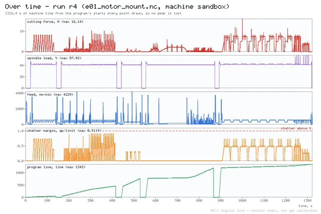
Unless you switch it off, every generated program runs to the end on a hidden copy of your setup, starting from the part as it is now. Studio probes the result for overcuts and leftover material at 0.02 mm, finds collisions and rapids into stock, and says where the tool cannot reach. Operations that chatter or overload are rewritten and run again, up to four rounds.
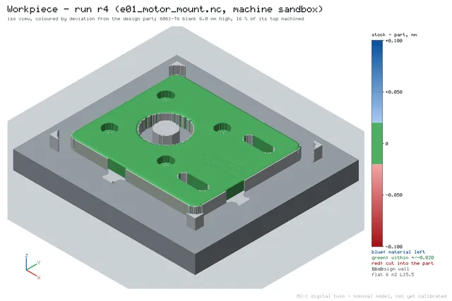
Measured in the twin with nominal machine parameters.
Simulated with nominal parameters until the MC-1 prototypes are calibrated against the twin.
Over MCP an AI assistant imports a shape with geometry_import and has the CAM write the program with program_generate — then checks, simulates and optimizes it on the twin like any other program. It describes shapes as data: outlines, text, formulas.
So that you know when to reach for another CAM.
For three-axis parts on the MC-1, usually not. For four or five axes, turning, STEP models or another machine, use the CAM you know; Studio checks and simulates its G-code like any other program.
The CAM is part of Studio. The free Learning edition has pockets, contours, slots, holes, text and V-carving, and 3D parallel finishing. Maker and Pro add adaptive clearing, every 3D finishing strategy, rest machining, two-sided parts and nesting — see Pricing.
No. The CAM workspace works without AI. An assistant is another way in — for example to describe a part in words.
Yes. The CAM runs on your computer. With a local model in LM Studio or Ollama, nothing leaves your computer even when an assistant drives it.
It is computed for the MC-1 with nominal parameters — the physics model's estimate — and then run in the twin. Each MC-1 is to ship with a twin profile set to its own measurements, so the numbers will follow your machine; on any other machine treat them as a starting point.
Open the CAM workspace, place a shape on the blank and run it in the twin — the program that comes out is ready for the MC-1.